LG201: IoT Prototype Development - Digital Fabrication
2a: Software Evaluation
SolidWorks or Fusion 360, that’s the question. A few articles later the general opinion seems to be, they’re both great, but Fusion is maybe better suited to designers, whilst SolidWorks is more suited to engineers. I land in the first category so let’s see how I get on.
So, let’s launch Fusion 360 and click Create Sketch, I’m in a reassuringly familiar environment, a 2D vector design space. A few web searches and I can draw shapes, step and repeat objects on a grid or around a point, this is great. I can even bring objects in from Adobe Illustrator, but the feature that stands out is Sketch Dimension. I can create dimensions that look like they come off an old isometric projection drawing, but most importantly I can change them and it alters my drawing.
When I used to work in Desktop Publishing, my pet hate was operators who placed things visually, If you want a 10 cm circle in the middle of an A4 piece of paper, it’s X position is ((210/2)-10) and its Y position is ((297/2)-10), that’s where it needs to be, so don’t guess… TYPE IT IN!
So this is how I approached building my Proof of Concept, you can imagine my excitement when I then discovered Parametric Modelling.
PageWidth = 210,
CircleDiameter = 10
CircleX = ((PageWidth/2) – CircleDiameter)
Now I only have to do the maths once, changing either the PageSize or CircleDiameter will recalculate CircleX for me. If I’m going to cut the circle out I could even add some tolerance for my 3d Printer, then just set that tolerance to zero when I go to production, this is great.
Now we’re comfortable in two dimensions, let’s leave our sketch and start working on the third. Extrude, Combine, Fillet, Cut, Split and Shell, these enable us to create all the shapes we need at this stage. We add more sketches to modelled surfaces to add more elements to our design.
This is a great bit of software, let’s try and create a proof of concept for my Thing.
2b: Proof of Concept
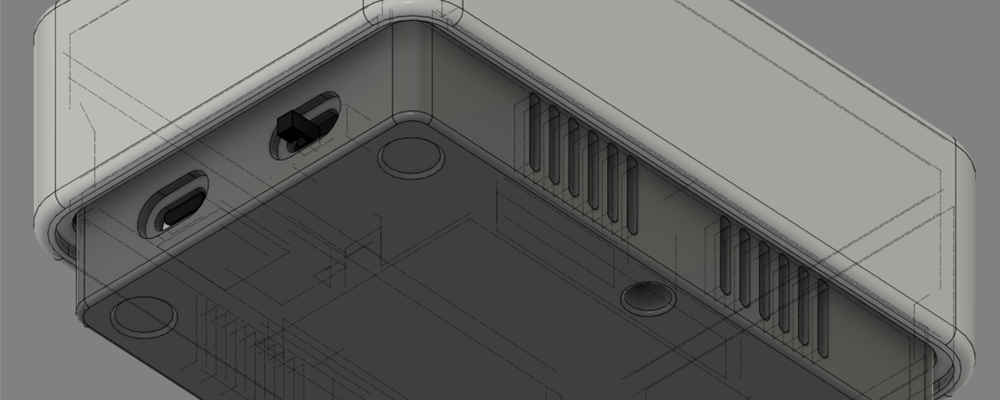
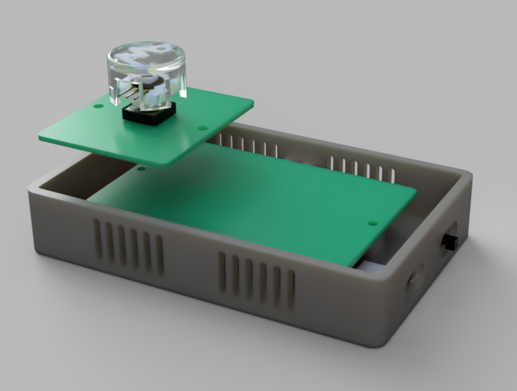
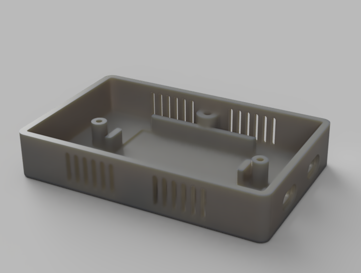
The starting point for our case design is the Perma-Proto boards from Adafruit. Adafruit has created Fusion models for most of their components, so I can import the ½ and ¼ size boards, and also the Hazzah36, we’ll have to create some of the other components ourselves.
I’m going to try 4 different fixing methods in my prototype:
- Snap fittings for the LED ring.
- Brass threaded inserts for the boards.
- Tapped screw holes to hold the lid and the base together.
- Plastic welding for the on/off switch.
Once we have created the two elements for output (the case and the base) we simply export them as STL files for printing. Once they’re ready we'll run our tests against them.
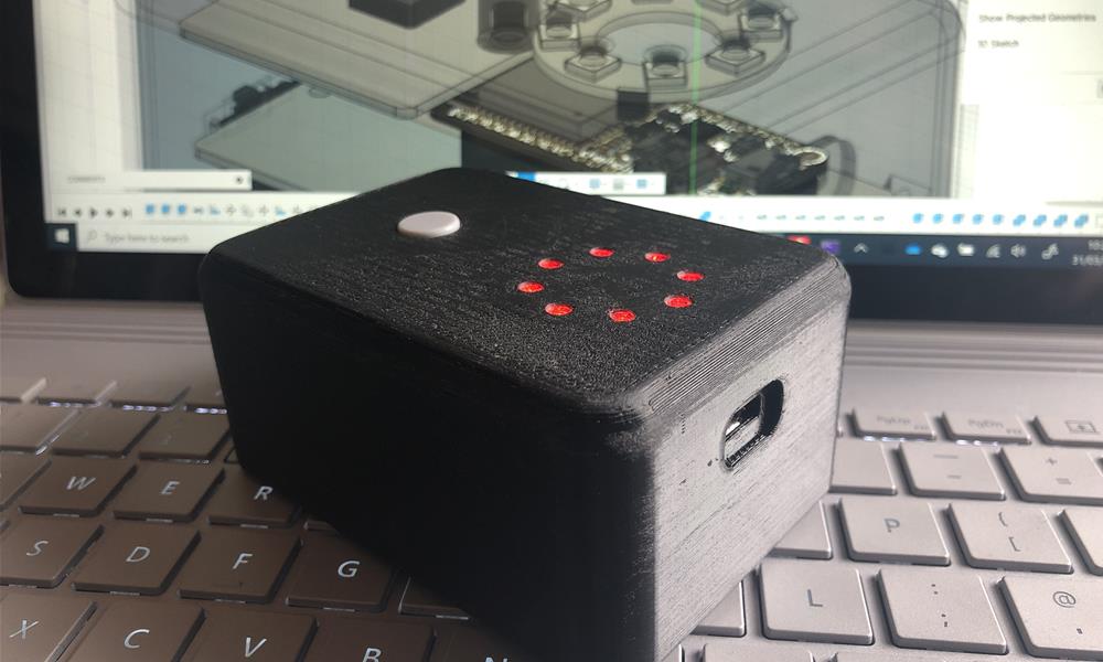
Test 1 - Does it look good?
This is slightly subjective, but nope it doesn’t… and I don’t think anyone is going to disagree with me on this one. However, as a designer, I know beauty isn’t subjective, there are rules!
The case looks like a cheaply finished lump of black plastic, it looks like a power block. The distinctive layered finish of 3d printed plastic has connotations of cheapness, this means the simplicity of the design is lost without a clean finish.
There is work to be done here, more design required, we need to sell the concept of the finished product, this case fails to do that.
Test2 - Do the fixing techniques work?
The snap fixings did exactly that, snapped before I even got the LED ring in position, the recesses for the LEDs in the top of the lid also needed more tolerance for them to take the required position. The article ‘Guidelines for Additive Manufactured Snap-Fit Joints,’ [1] highlights the issue of creating Snap-Fit Joints using additive manufacturing and with our cantilever beam running on the z-axis, we have the weakest possible outcome, this needs rethinking.
Brass threaded inserts worked great, I threaded the longest M3 bolt I had onto the insert, warmed it over a candle and then pushed it into place. Again, slightly more tolerance would be good, I had to warm these more than I would have liked and they started to deform the plastic around them. But good now I know I need a slightly bigger socket, Parametric Modeling means changing just one variable to deal with this.
I ran an M3 tap through the holes, we have threaded holes… simple and effective, but how strong?
Plastic Welding seems to work, I pushed the switch onto the pins and melted them against the back of it to fix it in place. It rattles slightly, may be needed to clamp it or superglue it against the case first. A Product Autopsy [2] on an old General Electric Walkie-Talkie shows this is, or was in the ’80s, an effective method of joining plastic items together, I kind of like it’s simplicity. But it’s also permanent so not great if your soldered wires snap off.
Lessons learned here to take into the next iteration.
Test3 - Do the components fit in the case?
Yes, they do, a useful rule is to make sure when you have components in two parts of a case, your leads are long enough that you can easily connect them whilst disassembled.
Test 4 - Does it protect the components?
Yes, it does, it’s its been knocking about in my bag for a week or so, but I’m struggling to get past how ugly it looks on my desk. Let’s make something we can be proud of, something that breeds confidence in our product.
One more thing, I don’t like having to put the USB port where the board is, I need to break it out in the next iteration.
2c: Design Guide
So this isn’t a Design Degree, right… but corporate identity is important, and things need to look professional, not because ugly devices and interfaces make my eyes bleed, but because the one things we need more than anything is trust.
I referenced an article about ‘Modelling trust dynamics in the Internet of Things’ [3] in the last section, the authors were concerned with the physical trust between devices, and the need for a trust management system. It strikes me that the lack of trust is more a societal issue, on two levels. The media loves a horror story about, I don’t know, Russians turning your freezer off so your food spoils, and we have previously given up too much data in scenarios we feel have been unfair to us.
Winning back trust will be a struggle for IoT manufacturers, good design and standardisation across devices and interfaces is where you can start to earn that trust. If something looks dodgy, people are going to presume it is.
So yeah, a little design project… I have a name, I mentioned it in my introduction, Wezmondo. I guess it could be anything but I’ll get dad points for using it, plus I have the domain!

So a few sketches later, and an hour in Adobe Illustrator and I have something I like. Its circuit board symbol pays homage to the maker community, but we move the green away from the industrial into the design realm by making it a bit more teal. Simple clean type, a logo that will work as an icon, a button and a website masthead. I’m happy with that, let’s give it a go.
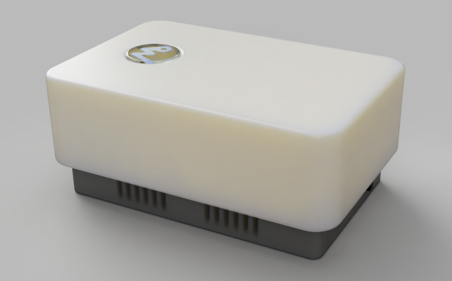
2d: Modular Case
Taking what we’ve learned from our initial proof of concept, we can start working on a design for our final case. I’m going to add some contrast both in colour and shape to start giving us an identity.
The base module will house the USB port and on/off switch, the lid will feature a combined input and output in the form of an illuminated button. This will be branded with the logo to reinforce our corporate identity and brand recognition. I’ve spent some time looking at objects around me, thinking about what makes them look trustworthy and what defines their beautiful. Sony, Amazon and Microsoft have inspired me, hopefully, I’ve learned from them.
Check out the first Wezmondo case, you should know what to expect from future versions now.
2e: Final Prototype
As I approach my hand-in date for this module, the University and the Country are in Corona Lockdown. The printed parts for my modular case are either sitting in an empty lab or stuck in a queue awaiting the operators return.
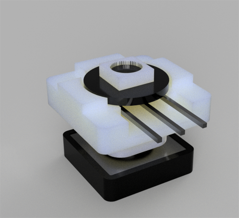
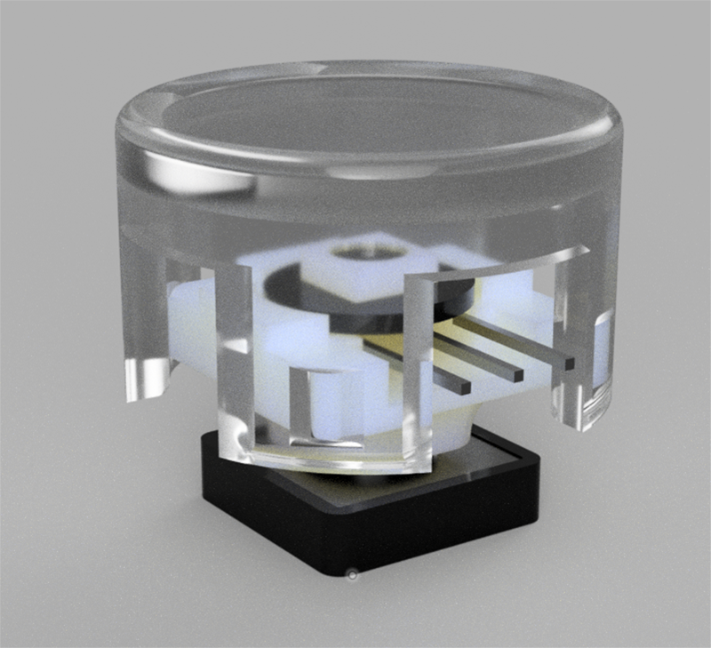
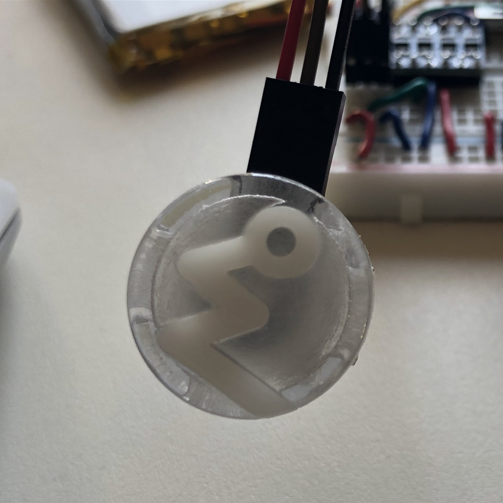
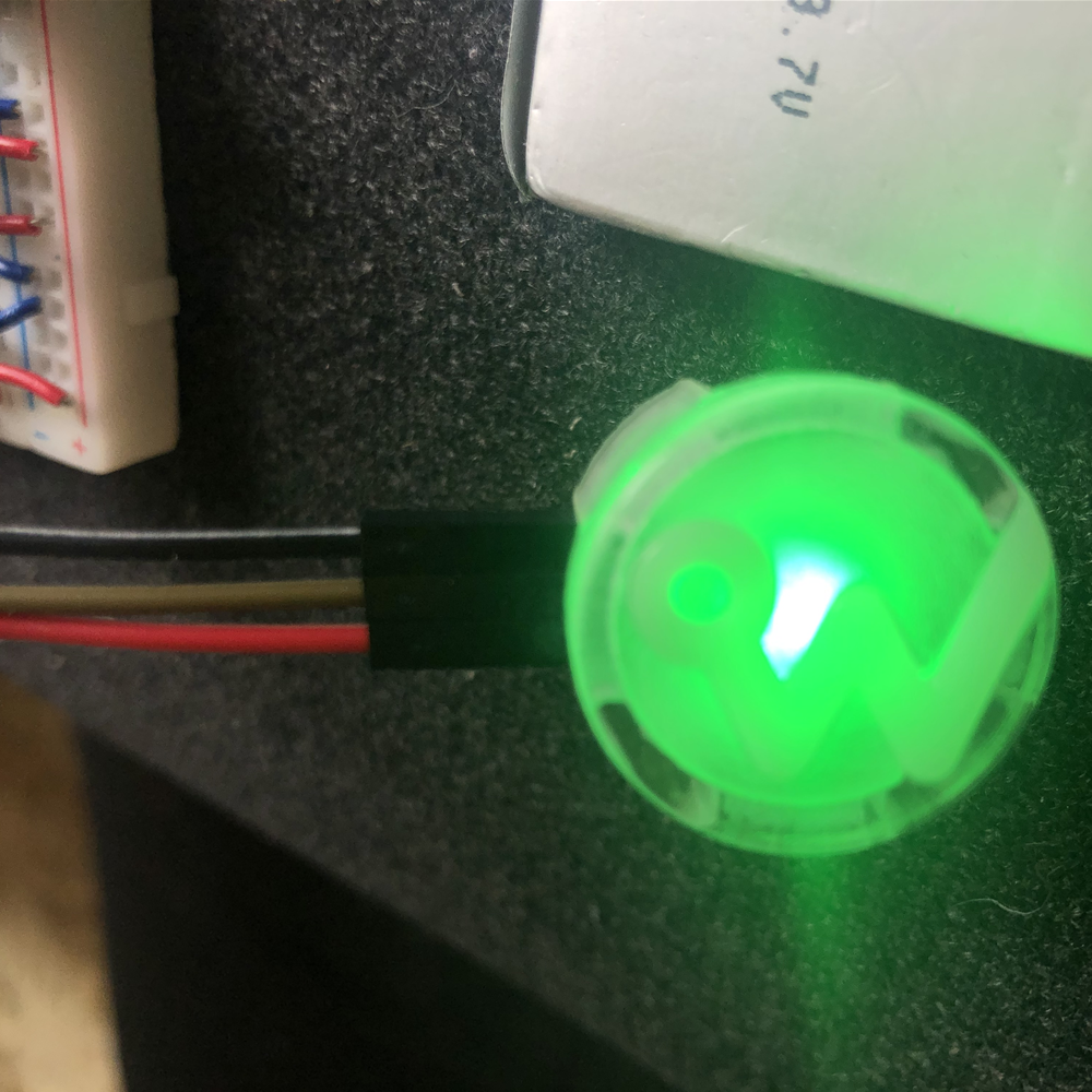
The major unknown of my new design is the Illuminated Switch, I have sent this to an online manufacturer for two reasons. First of all, as I mentioned the 3D printing lab is closed, secondly the lab doesn’t print translucent filament.
Having read about the comparative properties of the three main 3D printing methods, [4] I took this opportunity to use PolyJet printing (SLA) for this part. It will enable me to compare both the quality and strength of this key part of the design. [5]
As far as post-processing goes, with only the initial proof of concept to work with, I tried to apply a technique I read about online. I used wood filler to fill the imperfections, sanded the model, and then sprayed it with primer.
I messed up the spraying, and then was fighting a losing battle to get it to look any good. Further research and testing are required in this area. I feel this might be important going forward.
My Final Thoughts
This will be submitted before I know how I did with my final prototype, but I enjoyed this aspect of the module and love using Fusion 360. The more I use it the better I’ll get and the greater understanding of how to get the most out of the manufacturing technologies available.
An important consideration is to try not to restrain design to work with prototyping technologies. Fixings that failed during prototyping follow both the BASF and GE Design Guidelines, so would work successfully in manufacturing.
Lets design what we want to produce, not what looks great when it comes off the 3D printer.
Update!
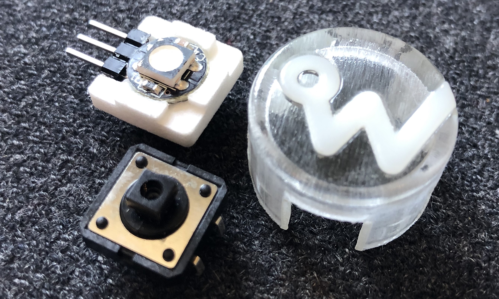
Still in Corona lock-down here, but, the 3D printed parts for the Wezmondo button have arrived. There is a marked improvement in accuracy using the PolyJet printing process, in fact, the tolerance in the snap-fit I allowed has resulted in a slightly loose join, so we'll alter that variable in the next prototype.
References
1. C. Klahna, D. Singerb, M. Meboldt, “Design Guidelines for Additive Manufactured Snap-Fit Joints.” 26th CIRP Design Conference, (2006). P319–322.
2. A. Milton, P.Rodgers, Research Methods for Product Design. (Laurence King Publishing, 2013), p33.
3. C. Fernandez-Gago, F. Moyano, J. Lopez, “Modelling trust dynamics in the Internet of Things”, Information Sciences, Volume 396, (2017), p72-82.
4. FormLabs, “How To Choose the Right 3D Printing Technology”, Retrieved from https://formlabs.com/blog/fdm-vs-sla-vs-sls-how-to-choose-the-right-3d-printing-technology.
5. A. Cazón, P. Morer, L. Matey, “PolyJet technology for product prototyping: Tensile strength and surface roughness properties.” Proceedings of the Institution of Mechanical Engineers, Part B: Journal of Engineering Manufacture, 228(12), (2014). p1664–1675.